Previously in the posts, GDT was the topic and the Wikipedia article with the code snippet was basically setting up kernel code segment and kernel data segment for paging. Remember the granularity flag, this was set to units of paging or in other words, set to 1. Let’s get into paging for this blog. It is highly relevant to the capstone, as the team is implementing a paging scheme within the final product, the Minimalistic OS.
As a reminder, both segment and paging are types of memory management methods. The virtual memory is actually a label to call a memory process of which the RAM/physical/main memory works together with a secondary storage device, such as a hard disk. More details about this virtual memory — later!
Sort of? Paging is a way to make the individual processes running feel like they are the only ones running on the disk. Much like a book, the reader is fixed on all the information contained on one page, then continued to the next page, however still solely focused on the page at hand. Another book related perspective could be that the author has their whole masterpiece on a continuous paper spool. To make a book, the spool is divided into equal sized chunks (pages) and stitched together to make a book.
With paging, a very nice and convenient sequenced logical memory space is provided for each of the programs. This is usually 4KB chunks or pages. However, this is all an illusion, as these individual processes are not actually alone, they are joined by others who also take part into this grand illusion, known as paging. Continuous memory allocation is what the individual processes will be using within the logical memory space probably is not continuous (or at least has the option of not having to be) within the physical memory space, in fact, this was a main driver for the creation of paging memory management.
created in pptx
Paging will require a type of look-up table or what is known as the page table, which holds all the pages. This table will be pointed to from a paging directory entry. In this table the logical address (the one the illusion-ed individual process will be using) will be mapped to an actual, no illusion, physical memory address or if using virtual memory scheme then, there is a possibility the mapping will be to a special place within a hard disk or the like. However, even if using a virtual memory scheme or not, the page table will map the illusion logical memory to a physical place in memory.
Let us first start off with some chunk located in the logical address space. This logical address will have two pieces to its address: selector and offset. The selector will be used to point to something handy in the descriptor table, of which will be the particular segment descriptor. The offset will be used with the segment descriptor to create the linear address. The linear address contains the page directory entry, page table entry, and the offset within the physical address hosting the page frame.
Virtual Memory Purpose
Virtual memory was originally thought to help out the limitations of a RAM/main memory size. As stated before, the virtual memory scheme is a usage between the RAM/main memory and a secondary storage device, such as a hard drive. The RAM/main memory will accumulate memory chunks (pages), with an allocated size, all the same for paging granularity, then begin moving the unused memory chunks (pages) into a designated storage place within this secondary memory device. In a sense, the virtual memory scheme creates another illusion of a huge and ample space “main memory”. However, in reality, this actually is far from the case.
We have all these unused pages/memory chunks within the secondary storage device waiting, once they are needed, they are placed back to the RAM/main memory place. The page table is consistently working to keep track of all these memory chunks. It can be a daunting task, surely!
Troublesome Paging
Disk thrashing and fragmented processes are the main issues with the use of paging. If you were to use segmentation memory management these are not issues, however with segmentation you are not using every last available memory space and memory fragmentation effects will be seen soon. Trade offs.
Disk thrashing limits application-level processing by page faults and over worked virtual memory abilities. It is data swapping at its limits! The moving of data does not allow for effective storage in the physical memory.
fragmented processes are processes which really don’t have all that they need to carry out their purpose. This becomes present when the hosting of the data paging is not adequate enough to piece all together during the use of a process from physical memory.
Best to decided what is the goal of your system — utilize main memory effectively (paging) or aim for fast access by processor (segmentation). Modern systems tend towards paging and a hybrid of the two types.
Now our team is focused on the protected mode learning and building. A great binary data structure used by the x86 Intel processors is the Global Descriptor Table (GDT). Think of it like a barcode. With any data structure its means are to provide a usage framework, and for the GDT, this framework created generally includes memory areas or segments described. For this week’s blog the goal will be to explain the Wikipedia Netwide Assembler (nasm) assembly language implementation of a generic GDT which opens up all 4GB of memory to a usable state. This code is free and accessible, therefore it also could entice the reader to go down the various rabbit holes during a visit, as wiki is never in short supply!
Nope. You do not actually need to make one of these IF you are using a bootloader mechanism which will do this type of work for you, i.e. GRUB. And… if you were to utilize GRUB and become determined to create your own GDT within, as in write over the already-there-GDT, a “triple fault” will occur and the computing machine will reset. Sad day!
However IF you are not using a bootloader mechanism and aim to have memory protection once your OS is initialize, yes, and emphatic YES! Unless you are making something uber special and some how do not need GDT for paging mechanism or similar.
Courtesy of giphy
What?!? — x86 segment descriptor?
It shall be noted, the GDT data structure can do more than describe memory chunks/segments, however these extra things are not needed for our project at the moment, therefore detailed dives into all the possibilities of a GDT data structure will not be commenced here.
Segment descriptors are used by the x86 architectures as a way for translating a logical address to a linear address — the segment descriptors are here to describe the memory segment assigned within the logical address. Linear address is a virtual address, an address where a thing lives from the understanding of the executing environment. The linear address does not actually have to be a physical address, especially in the realm of virtual memory usage, which is applicable here. You can think of this as a form of address “normalization”.
Segment descriptors will contain at least the following:
Base Address
Segment Size/Limit
Access/Privilege Rights (think memory protection!)
Flags
created in pptxcreate in pptx
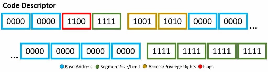
Through the descriptor framework we can make things, such as the code descriptor and data descriptor, shown above. These examples will also be a visual for the bits used within the Wikipedia code snippet to be explained.
In our code example, soon to be explained with a fine-toothed comb, there are two segment descriptor data structure implementations: code and data. I mean if you count the “dummy” one full of 0’s, then i guess we actually have three. Each will have different bit set-up, however still based off the four attributes listed above. You may note, the scheme of which bits are associated with which attribute are not exactly… orderly, there are a few jumps around and continuing — however, all will be explained!
Base Address
This is your 32-bit linear address, where we are stating the starting of the memory segment. If your architecture is 64-bit based, this is ignored.
Segment Size/Limit
This is your 20-bit value, where we are stating the maximum allowable addressing unit. This could be 1 byte units or 4 KB units. Here, you just want to place the address of the last accessible data place + 1. If your architecture is 64-bit based, this is ignored.
Access/Privilege Rights
This is your 8-bit value, where you highlight description of access. Four bits describe the presence of the segment, ring level of privilege, type of descriptor. The other four bits describes the type.
[ P . DPL . DPL . DT . Type . C|E . R|W . A]
P – segment presence. If the bit value is 0 then an exception will be given if referred to this segment and if the bit value is 1, then no exception will be given if segment is referred to.
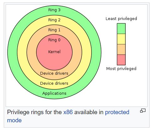
DPL – (two bits) – Descriptor privilege level field or ring level to access this descriptor. Two bits allows binary-11 or decimal-3, up to ring 3. The graphic below depicts the ring level meanings and usual privilege-based assigned.
Courtesy of Wikipedia
DT – literally a fixed one, descriptor type, this is a descriptor, must be one.
Type – This is a huge switch. If this value is 0, then descriptor is a data segment and if the value is 1 then the descriptor is a code segment. You will see the underlying other bits which base off this set/not set of a bit. For stack/data segments use of E, R, and flag D. For code segment use of C, W, and flag B.
[C or E] E – Expanded-down or direction bit. (type – 0) meaning if the bit is 1 then the segment will grow in a downward fashion, while a bit of 0 will grow up, the offset will be less than the limit. C – Conforming bit. (type – 1) meaning is the bit value is 1 then the code can be executed from less=privileges levels and if the bit value is 0, then the code segment can only be access by this ring and above.
[R or W] R – Readable bit. Not to use with code segments (type – 1). (type – 0) read access is not abled when set to 0 and read access is abled when set to 1. W – Writeable bit. Not to use with data segments (type – 0). (type – 1) write access is not abled when set to 0 and write access is abled when set to 1.
A – Set to 1 by hardware/CPU when segment is accessed and set to 0 by software.
Flags
This is your 4-bit value, where you describe the granularity, operand size, and availability for the system.
[ G . D|B . L . AVL ]
G – granularity this is tied closely for paging work. If the value at this bit is 0, then units of bytes are utilized (max 2^20 bytes) known as byte granularity and if the bit value is set or 1, then unites of 4096-byte pages (max 2^32 bytes) known as paging granularity.
[D or B] D – Default operand size. If the value of the bit is 0 then it is 16-bit max 0x0000FFFF and if the value is 1 then 32-bit segment. B – Big operand size. If the value of the bit is 0, same as D and if the value is 1 then the maximum offset size for the data segment is 32-bit 0xFFFFFFFF.
L – long-mode flag, ability to use 64-bit segment rules. If the value is 0 then not-64-bit and if the value is 1 then 64-bit applies (D must be set to 0 for proper usage).
AVL – Available for software use, not utilized for hardware, it is like a wildcard flag you could use within your program or a reserved flag.
Example of GDT
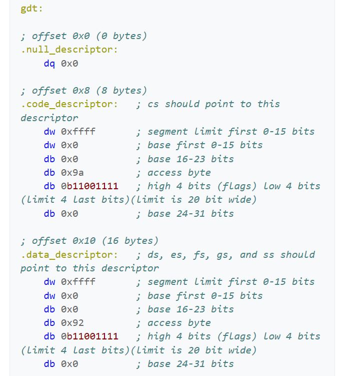
Below you will view the nasm assembly code for a simple gdt. After the photo, we will dive into what all this means.
Courtesy of Wikipedia
Two things to point out here in this photo. First, the access bytes would have been more helpful to the reader if these were given in binary, rather than hexadecimal (‘0x9a’ and ‘0x92’). Secord, the assembler does not have something lower in amount of bits than ‘db’, which is 8-bit direct bits. If it did, it could help the reader better understand the separation that is actually going on within the ‘0b11001111’ and ‘0b11001111’, where we are forced to combine the flag bits with a portion of the limit bits.
I hope by reading this code you would agree the jumping and disorderly placement of bit meaning for these descriptors. However, this is probably due to the historical or general hardware ease of interpretation with the ending machine code after the assembler helps out.
Now, where is my comb?
We are establishing three different segments: null, kernel mode code, and kernel mode data. There is no user space in this or the task state segment (TSS), of which are common frameworks one would set up for a minimalistic OS. Mainly for the user code and user data the ring would be three instead of zero. For the TSS, the ring would be one. I digress. In this code snippet, the aim is to open up and access 4 GB, 0x0000000 to 0xFFFFFFFF. Therefore, the base address will be 0x00000000 and the limit will be (0xFFFFFFFF – 0x00000000) + 1, or 0xFFFFFFFF. You will see the use of the flags for this large of a limit.
The null descriptor segment is used by the CPU only and should not have any data in there. The Boch emulator will give a limit exception if you did not set one of these up. Since the null descriptor is 8 bytes, it could be used for the pointer to the GDT, which is 6 bytes. However, in this example all the bytes and bits are set to 0.
created in pptx
The 8 byte kernel mode code descriptor segment has the following:
Therefore, to build out this segment descriptor, we use the scheme within the pptx diagram above. To speak on the access rights of 0x9a or b1001 1010 in detail, let’s begin. The segment presence is set, therefore no exception shall be expected when referring this segment. The two-bit DPL is 00, therefore this code descriptor has ring-0 or highest privileges. Makes sense, you don’t want malicious programs or blissfully unaware users to take advantage of the kernel code descriptor. The DT is set, obvious, as this is indeed a descriptor. The type is given as set or announcing this is a code segment, meaning the use of C, W, and flag B. The conforming bit is not set, therefore this code segment can only be accessed by its own privilege ring and higher (however in this case, it is already the highest level of privilege). The writable bit is set, therefore write access is granted. Finally, the Access bit is not set, therefore it is currently in software’s hands. This final bit being not set is a little odd, generally you want to keep this not set and let the hardware have its turn. Oh well, this is Wikipedia code snippets… As for the flags, b1100, there is more to uncover. The granularity bit is set, therefore paging units are being utilized. The operand size is set, meaning because the type was set in the access bytes, we are granted to use the big opcode size, of which if set, which it is, the the maximum offset size for the data segment is 32-bit 0xFFFFFFFF. This is allowing us to be able to reach the actual desired limit. The long-mode flag is not set, therefore 64-bit rules will not be applied. Lastly, the AVL or wildcard flag is not set or being used.
created in pptx
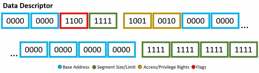
The 8 byte kernel mode data descriptor segment has the following:
You might notice, wow this is very similar to the code segment descriptor — right you are. It seems whoever put this code snippet together wanted the only different between the two, well, very slim. Nevertheless, lets dive into it. The access bits of b1001 0010 will be our first subject. The segment presence bit is set, no exception will be given if this code segment is referenced. The DPL two-bits are set to 00, of which is ring-0, highest privilege. The DT is set, well yes, this is a descriptor! The type given is not set, therefore it is a stack/data segment type. The use of E, R, and D-flag will be applied. The Expanded-down or direction bit is not set, therefore augmentation will begin upward, in other words the offset will be greater than the limit. The readable bit is set, read access is enabled. Once again, the access is set to software, and still questionable, the reading in other resources state this should actually be left to 1 as the CPU/hardware will be accessing it. Now for the flag byte, b1100. The granularity bit is set, therefore units of paging will be utilized. We had type 0, therefore the default operand size will be used. This default operand size bit is set, meaning 32-bit segment rules. The long-mode flag is not set, no use of 64-bit rules and the wild card or AVL bit is not set meaning this is not used either.
From the code snippet, their comments show the offsets between the different descriptor segments is 8-bytes. This will be important and handy when using these in the actual initialization of the kernel file.
Now we have this GDT descriptor, what next?
Meet opcode lgdt !
During the initial kernel set up, we are tasked with setting up the segment registers, of which we need this framework to be described. Who better to ask for a description of descriptors than our GDT? We will call this opcode along with the value we will be storing at a pointer to the GDT descriptor, another framework. Man! We will now be embedded our GDT framework into a GDT descriptor framework. The GDT Descriptor will hold the offset (linear address) and the size of the GDT. Bam! Now we have connected things and can start adding entries of code and data segments.