Spring Break 2022
March 28th, 2022Ah, spring break week, a time to relax. Right? No, not the case. There was finally a week to spend time diving into learning about software-hardware interaction. There was a kit online, found awhile back, and this seemed to be a great time to roll up the sleeves and begin working on wiring, programming, and testing a mini computer.
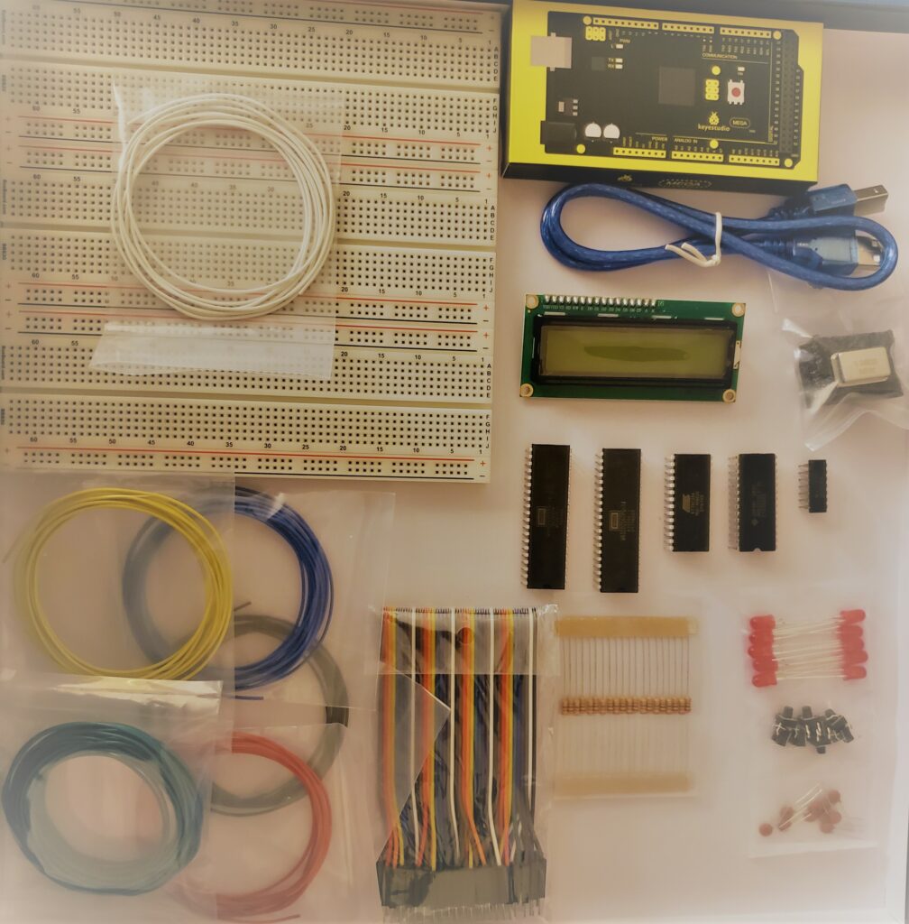
The kit and some associated video links can be found here.
Background
Since the OSU course 271, intro to computer architecture and assembly, there has been a desire to build a physical model of a computing machine. This desire was one that could not be fulfilled by Arduinos or Micro:bits, it needed to be installing wires and use something other than a GUI with code blocks. The Ben Eater kit for the 6502 processor arrived, the challenge was gladly accepted.
What is it?
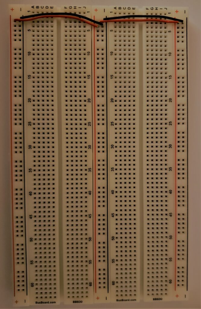
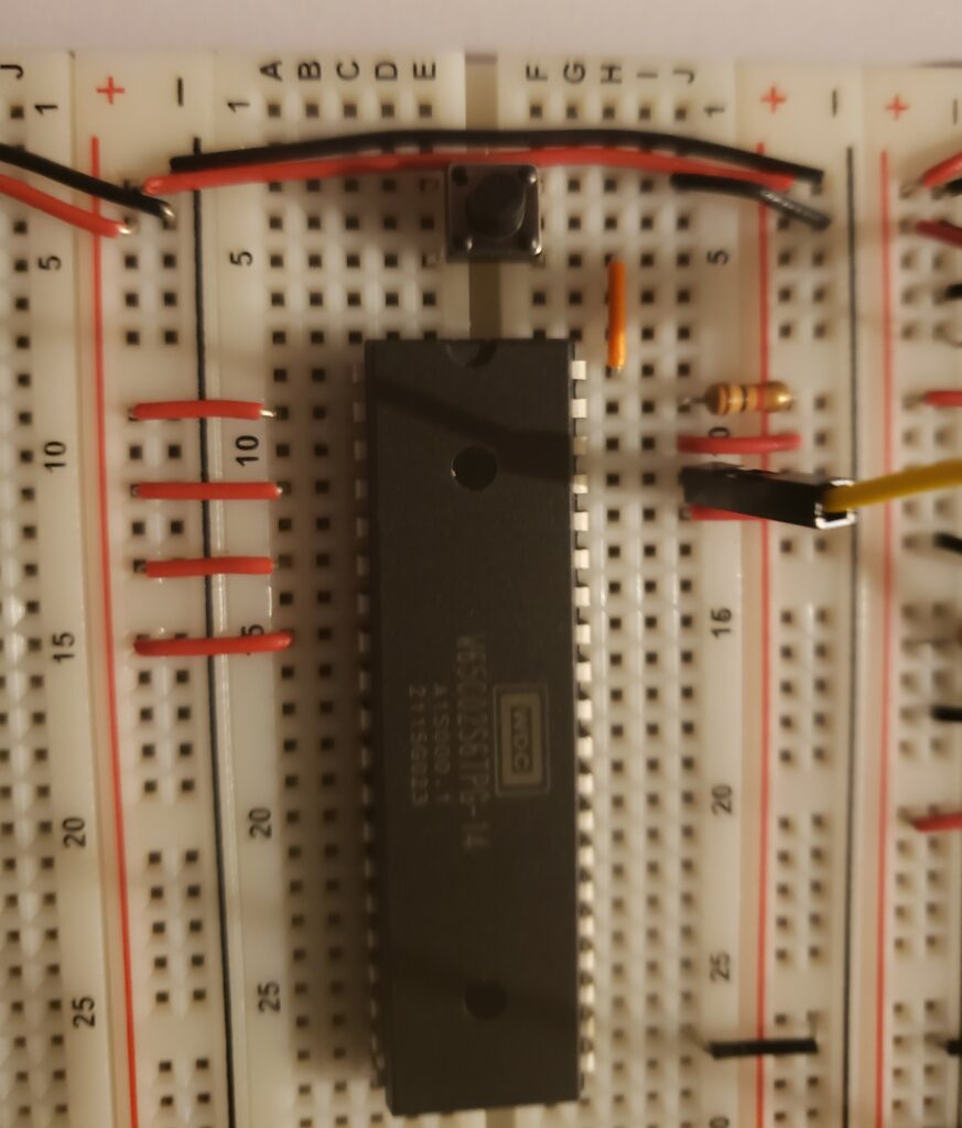
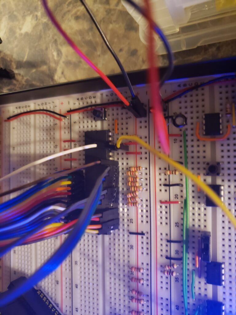
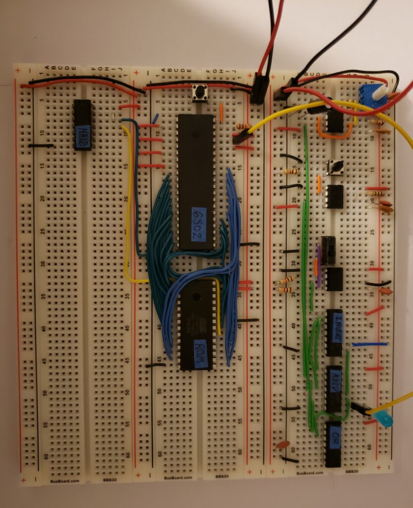
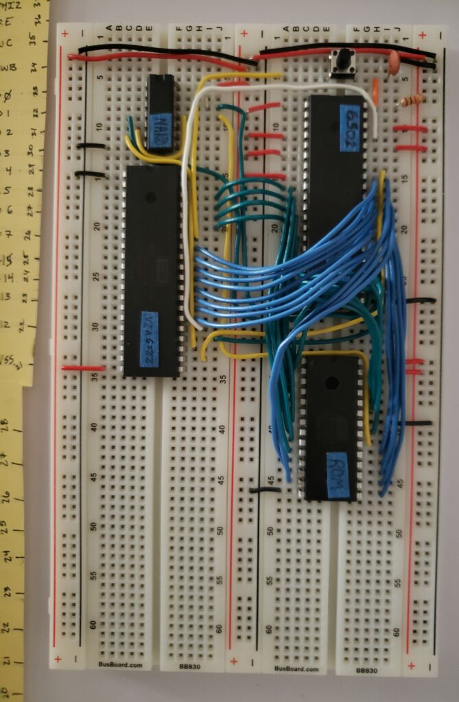
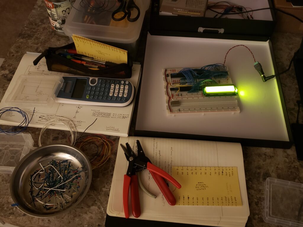
Ultimately it is making use of a Western Digital 65c02 processor chip, Western Digital 65c22 versatile interface adapter, common NAND gate (4) chip, ATMEL AT28c256 ROM chip, Hitachi HM62256LP-70 RAM (used as a stack) chip, Hitachi LCD, knob dial for LCD contrast input, resisters, capacitors, 5V input, 1Mhz clock chip, and assorted 20mm insulated wires — on a few breadboards.
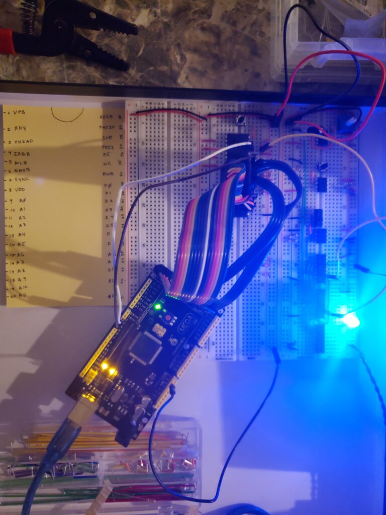
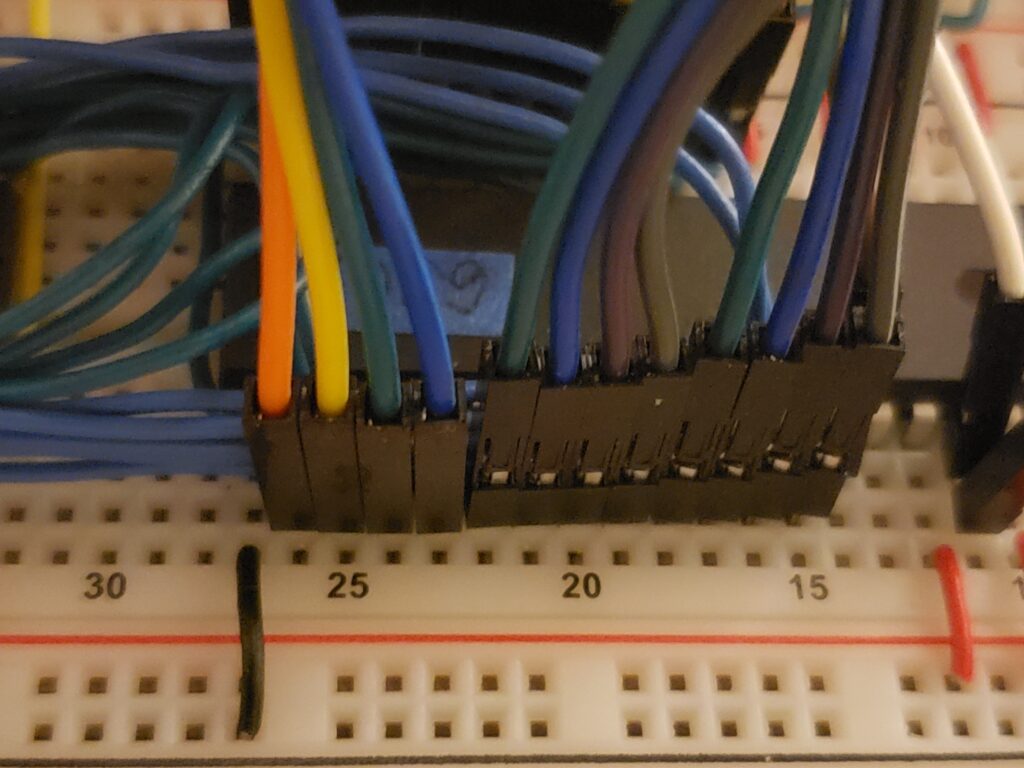
Testing connections was carried out with the MEGA Arduino connection ports, no fanciness with expensive purchase, as Ben states within one of his videos. Less expensive, however over the project, you will dedicate much time to connecting each pin, and in the proper order. Luckily, there is an output on the Serial Monitor. Here you will know if you flipped the pins, as the expected, for example ‘10001111’ would be ‘11110001’. Easy fix, just take the time to look at what this lovely monitor is trying to tell you and update your input probe wiring configuration.
Programming the ROM was carried out with the EEPROM programmer and this software. The assembler used was vasm. Currently, it seems all this was easier on a linux system, rather than the starting windows machine.
Good Practices
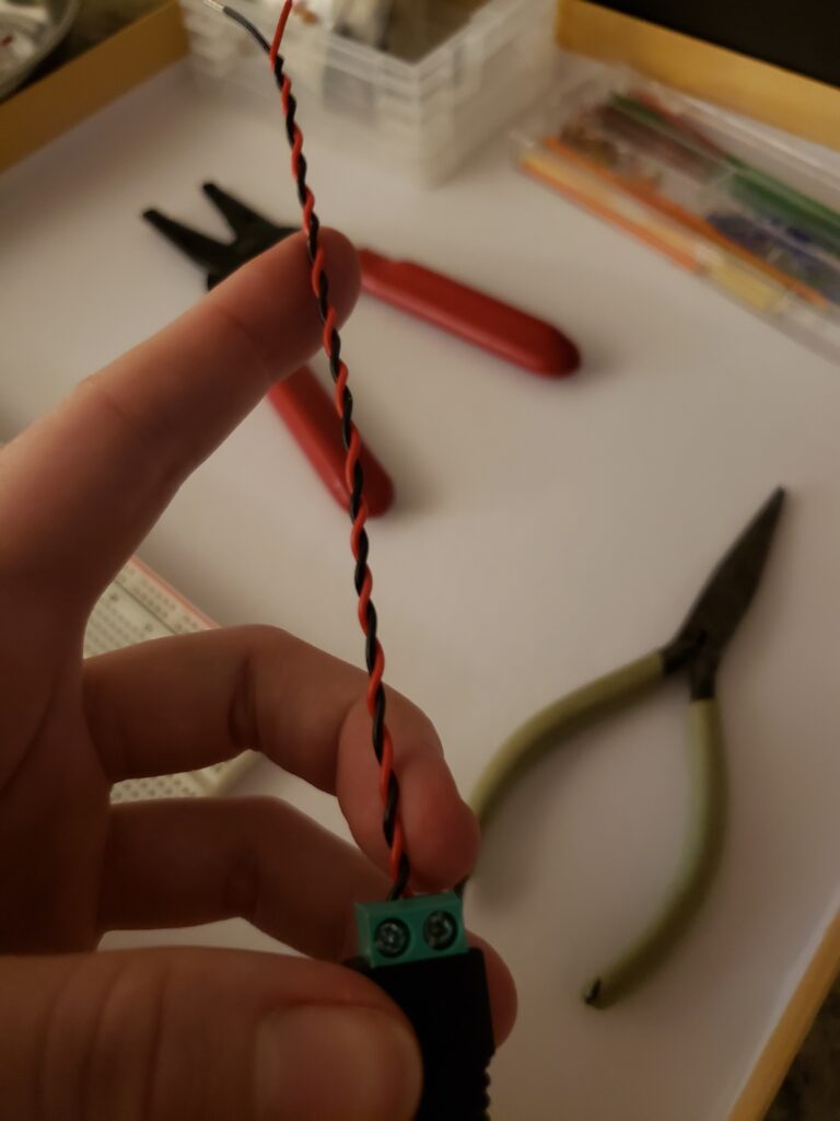
Do use some needle nose pliers, wire-strippers (aim for 24/26), and simple wire-cutters.
Do double check all connections of the piece you are working on, wires do like to shift, even on the high-quality breadboards.
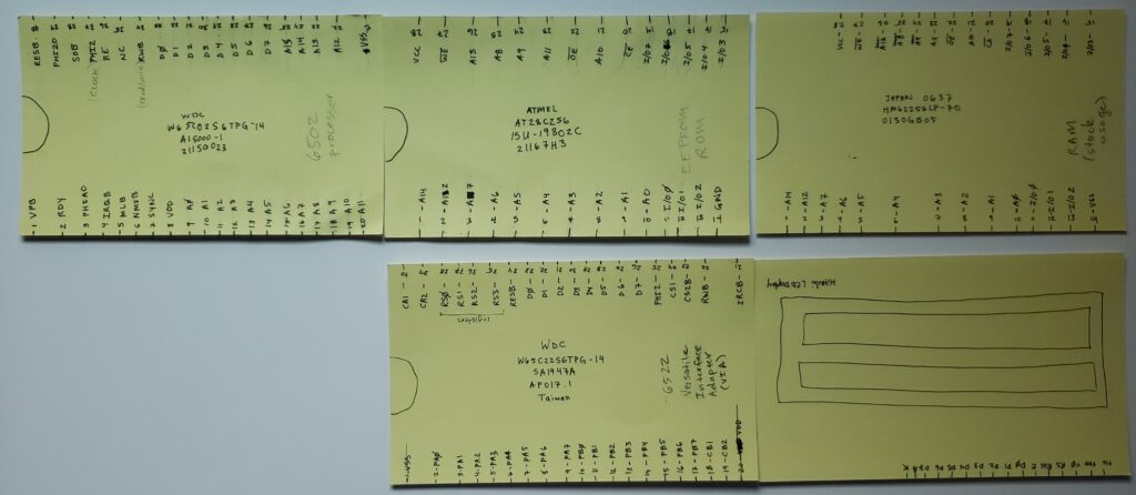
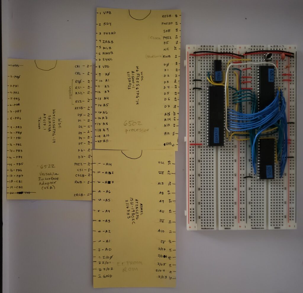
Do create index cards with mapping of pins, as the documentation is nice, however the little index cards let you move around and access the information clearly and even build out with a good representation of the chips.
Do take note of the issues you see, take the scientific approach of only updating one thing, run, compare to last — instead of changing multiple things at once and hoping for the best. 乁( ͡°ᨎ ͡°)ㄏ
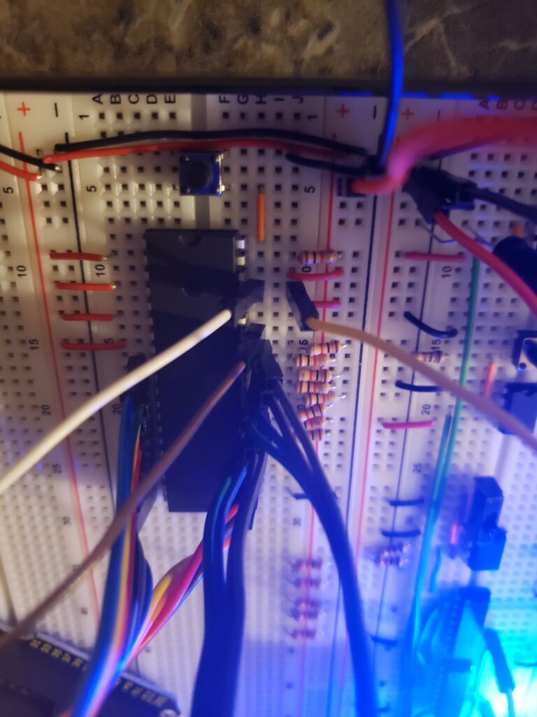
Do take extra care to make the wiring of the clock pin connections as short as possible, this is a help for the proper timing window for some of the pieces to have access to “valid” data chunks, nanoseconds off could affect, other connections do not need as much time investment.
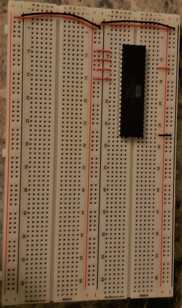
Do use a single color wire for data and address lines for help in not only understanding, some of the “buss” will carry over to other chips, having different colors helps to reassure the carry over will be correct places if you choose not to look at the pin mapping.
Do take breaks and work on something else, fresh eyes will be helpful when finding errors, almost like the mind is RAM, and you need to turn it off and come back, you don’t have the previous thoughts, you have something clean to work with.
Programming with a ROM
The video walk throughs showed programming the ROM is possible with either python (hardcoding opcodes and variables associated) or assembly language with instructions for the specific 6502 processor documentation. There are probably other languages to use, however these were the ones Ben Eater chose to utilize, of which the project was completed with.
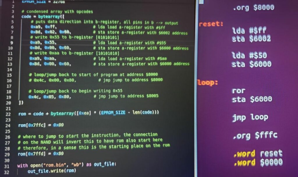
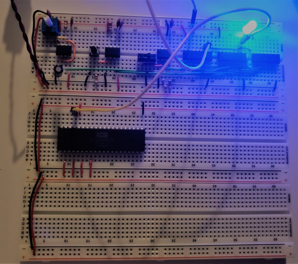
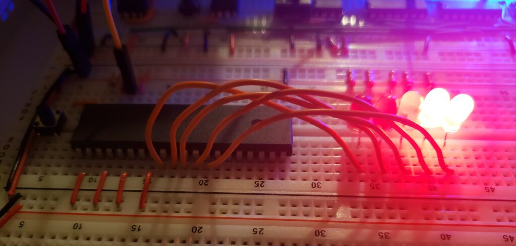
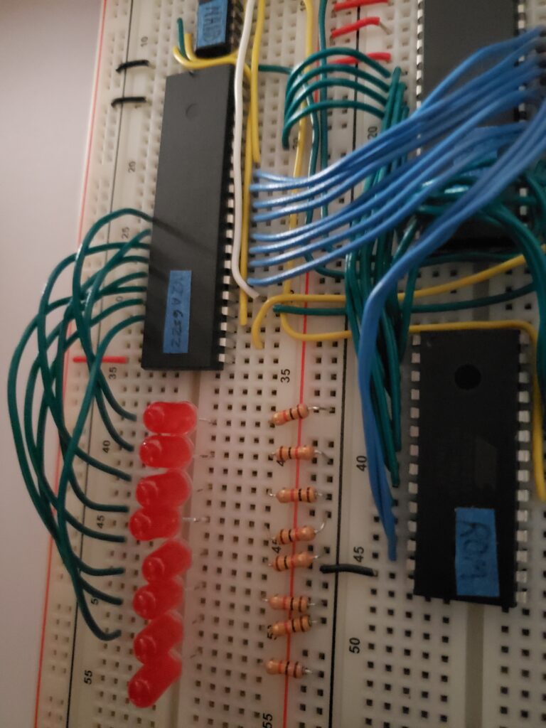
For the python code above, the goal was to see the optical illusion of blinking LEDs, which can be created by looping ‘01010101’ and ‘10101010’. Below you will find a video demonstration after the upload to the ROM chip and some LEDs are installed. You might notice the strange LED above the grouped LEDs, this is another module of Ben Eater’s kits, the clock module kit. It allows you to have a less-professional (in terms of clean signal transition to high/low) variable speed and for debugging/seeing each cycle on the Arduino MEGA — a push button for creating a “clock cycle”. This was useful to physically see the cycle needs for some of the instructions outlined within the 6502 processor documentation.
For the initial assembly code you viewed above, a nice ‘ror’ was used to create yet another optical illusion of the ‘101’ seeming to move and wrap around the grouped LEDs, as you will witness in the below video. Please note, the ‘ror’ would mean to rotate right one bit, however they are moving left. What? Yes, this is because the wiring is set to have the starting bit to be the most-right LED. Again, optical illusion.
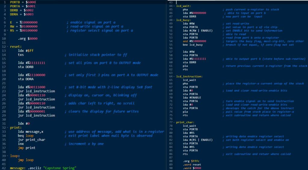
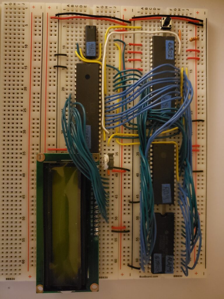
Before the RAM was installed, there was not a stack, therefore once the LCD was installed it would output some strange calls for memory address and jump to places of which were not within the program. Installing the RAM allowed use of push/pull values and was 100% needed for the final implementation. Here is final code used for the final project, all assembly. Code is well documented, therefore you don’t have to flip pages and read too much of the documentation if you do not currently have the time.
Maybe you are wondering — yeah, I see the code, how does this get on the ROM chip? Welp, you are in luck! Here is how. First, you will need to set up the EEPROM programmer that comes within the kit. Here are the step taken for ubuntu linux os:
username@computer:~$ sudo apt-get install build-essential pkg-config git libusb-1.0-0-dev
username@computer:~$ git clone https://gitlab.com/DavidGriffith/minipro.git
username@computer:~$ cd minipro
username@computer:~/minipro$ sudo make install
username@computer:~/minipro$ sudo cp udev/*.rules /etc/udev/rules.d/
username@computer:~/minipro$ sudo udevadm trigger
username@computer:~/minipro$ sudo usermod -a -G plugdev username
username@computer:~/minipro$ sudo cp bash_completion.d/minipro /etc/bash_completion.d/
Now you will be able to run the programming scheme with ‘minipro’ keyword as an environment variable. Nice!
For the python program listing above, here are the steps taken to get this program onto the ROM, it should be noted the python program is actually creating a file ‘rom.bin’. Consistently, you can check the contents of what you have created with this nice hexdump, the final hexdump listed later will be more legible for read ascii straight. The firmware is outdated, however it did not seem to effect the needs of the project. To speak about the flags really quick. The flag ‘-p’ is for program, ‘AT28C256’ is the ROM chip type used, ‘-w’ is to write, and ‘rom.bin’ is the file you are wanting written. One obvious error you could run into is not placing the chip with the half-moon in the direction of closest to the programmer chip locking level, this will output something to the console much along the lines of ‘No programmer found’. Check orientation and try again, a quick fix. There is also a nice indented sign on the programming port hardware to remind you. It seems tricky to re-install the little feet of the ROM chip, be patient, and don’t give up — check the orientation of the semi-circle at the top.
username@computer:~$ python3 makerom.py
username@computer:~$ hexdump -C rom.bin
00000000  a9 ff 8d 02 60 a9 55 8d  00 60 a9 aa 8d 00 60 4c  |....`.U..`....`L|
00000010  05 80 ea ea ea ea ea ea  ea ea ea ea ea ea ea ea  |................|
00000020  ea ea ea ea ea ea ea ea  ea ea ea ea ea ea ea ea  |................|
*
00007ff0  ea ea ea ea ea ea ea ea  ea ea ea ea 00 80 ea ea  |................|
00008000
username@computer:~$ minipro -p AT28C256 -w rom.bin
Found TL866II+ 04.2.86 (0x256)
Warning: Firmware is out of date.
  Expected  04.2.128 (0x280)
  Found     04.2.86 (0x256)
Erasing... 0.02Sec OK
Protect off...OK
Writing Code...  6.49Sec  OK
Reading Code...  0.40Sec  OK
Verification OK
Protect on...OK
For the assembly program listed above, here are the steps taken to get this program onto the ROM. Please note the ascii output not for the final project message of ‘Capstone Spring’, it is for the message ‘Hello world!’. The Volker Barthelmann and Frank Wille vasm assembler will, by default make their output file to ‘a.out’. Ben Eater creates the file and sets up the ‘oldstyle’ version clearly within his videos, therefore here not much detail will be listed. Source documentation can be found here. Quick note, the flags ‘-Fbin’ is for the ‘-F’ flag and ‘bin’ is the the output driver to be used, ‘-dotdir’ for use of any ‘.’ formatted call within the program, and ‘blink.s’ is the file name with all the beautiful assembly code written inside.
username@computer:~$ make CPU=6502 SYNTAX=oldstyle
username@computer:~$ nano blink.s
username@computer:~$ ./vasm6502_oldstyle -Fbin -dotdir blink.s
vasm 1.9 (c) in 2002-2022 Volker Barthelmann
vasm 6502 cpu backend 0.10 (c) 2002,2006,2008-2012,2014-2021 Frank Wille
vasm oldstyle syntax module 0.16 (c) 2002-2021 Frank Wille
vasm binary output module 2.1 (c) 2002-2021 Volker Barthelmann and Frank Wille

seg8000(acrwx1):	         126 bytes
segfffc(acrwx1):	           4 bytes
username@computer:~$ hexdump -C a.out
00000000  a9 ff 8d 02 60 a9 55 8d  00 60 a9 aa 8d 00 60 4c  |....`.U..`....`L|
00000010  05 80 ea ea ea ea ea ea  ea ea ea ea ea ea ea ea  |................|
00000020  ea ea ea ea ea ea ea ea  ea ea ea ea ea ea ea ea  |................|
*
00000000  a9 ff 8d 02 60 a9 e0 8d  03 60 a9 38 20 58 80 a9  |....`....`.8 X..|
00000010  0e 20 58 80 a9 06 20 58  80 a9 48 20 6b 80 a9 65  |. X... X..H k..e|
00000020  20 6b 80 a9 6c 20 6b 80  a9 6c 20 6b 80 a9 6f 20  | k..l k..l k..o |
00000030  6b 80 a9 20 20 6b 80 a9  77 20 6b 80 a9 6f 20 6b  |k..  k..w k..o k|
00000040  80 a9 72 20 6b 80 a9 6c  20 6b 80 a9 64 20 6b 80  |..r k..l k..d k.|
00000050  a9 21 20 6b 80 4c 55 80  8d 00 60 a9 00 8d 01 60  |.! k.LU...`....`|
00000060  a9 80 8d 01 60 a9 00 8d  01 60 60 8d 00 60 a9 20  |....`....``..`. |
00000070  8d 01 60 a9 a0 8d 01 60  a9 20 8d 01 60 60 00 00  |..`....`. ..``..|
00000080  00 00 00 00 00 00 00 00  00 00 00 00 00 00 00 00  |................|
*
00007ff0  00 00 00 00 00 00 00 00  00 00 00 00 00 80 00 00  |................|
00008000
username@computer:~$ minipro -p AT28C256 -w a.out
Found TL866II+ 04.2.86 (0x256)
Warning: Firmware is out of date.
  Expected  04.2.128 (0x280)
  Found     04.2.86 (0x256)
Erasing... 0.02Sec OK
Protect off...OK
Writing Code...  6.49Sec  OK
Reading Code...  0.40Sec  OK
Verification OK
Protect on...OK
Finished Project
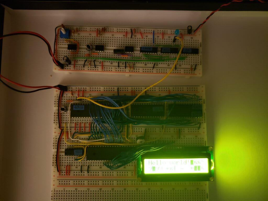
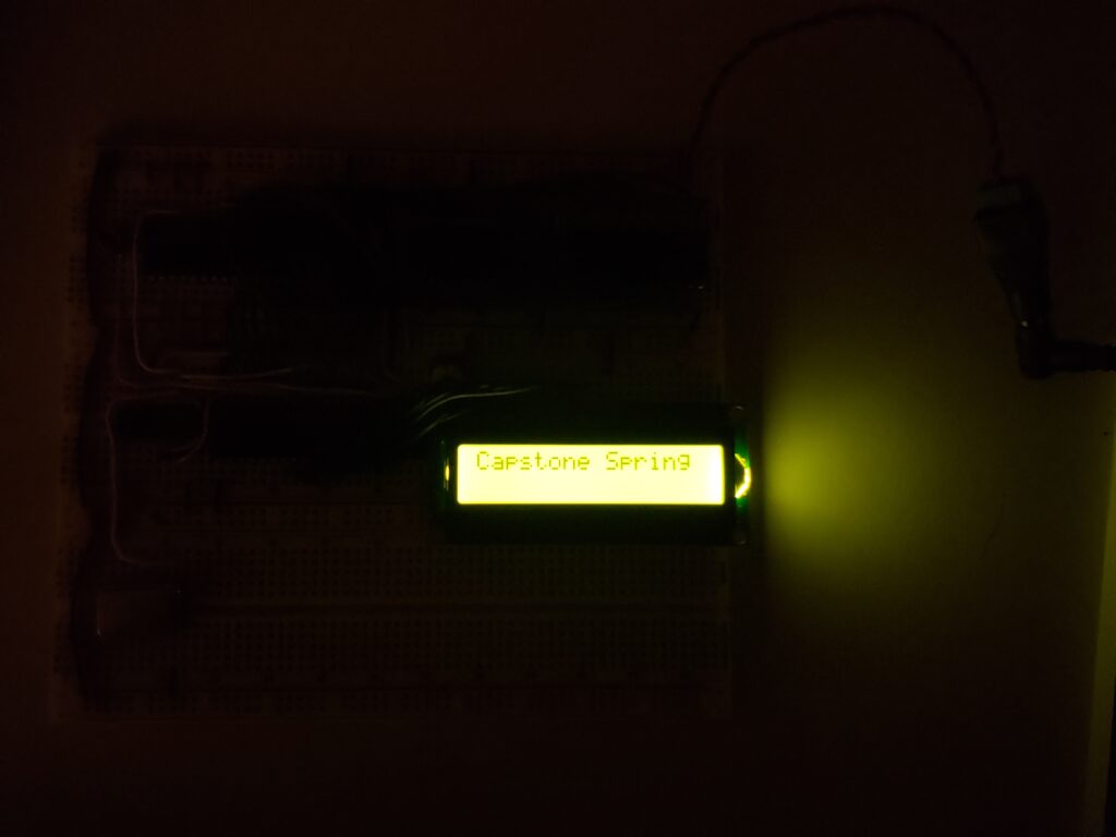
Here is a film of the programed project.
Ideally, this was a great project on many levels. The teachings of Ben Eater videos are easy to follow along with and he gives multiple ways of doing one thing on some of the subjects covered. He reviews the actual documentation from the chip manufacturers with a beginner’s mind. It could seem every pebble was flipped over for the hardware used within the project. Surprisingly, the trickiest thing about this project is the wiring.
Highly recommend.
Conclusion
For a week’s worth of time, including the time for delivery of the kit, one can create a mini computer on a bread board set. As a disclaimer, not all the details are listed here, as the thought was, the post should be light and fun with loads of media to get readers (hopefully) excited about building projects on a breadboard. It is a very good review of topics mentioned within the OSU 271 course and opens the mind to thinking in terms of the physical pieces of the topics. As a hands-on learner, this was a top-notch experience. Ah, it is over, the sweet spring break, back to school. Look for updates on the current course, Capstone in the upcoming posts.
Thank you for reading.