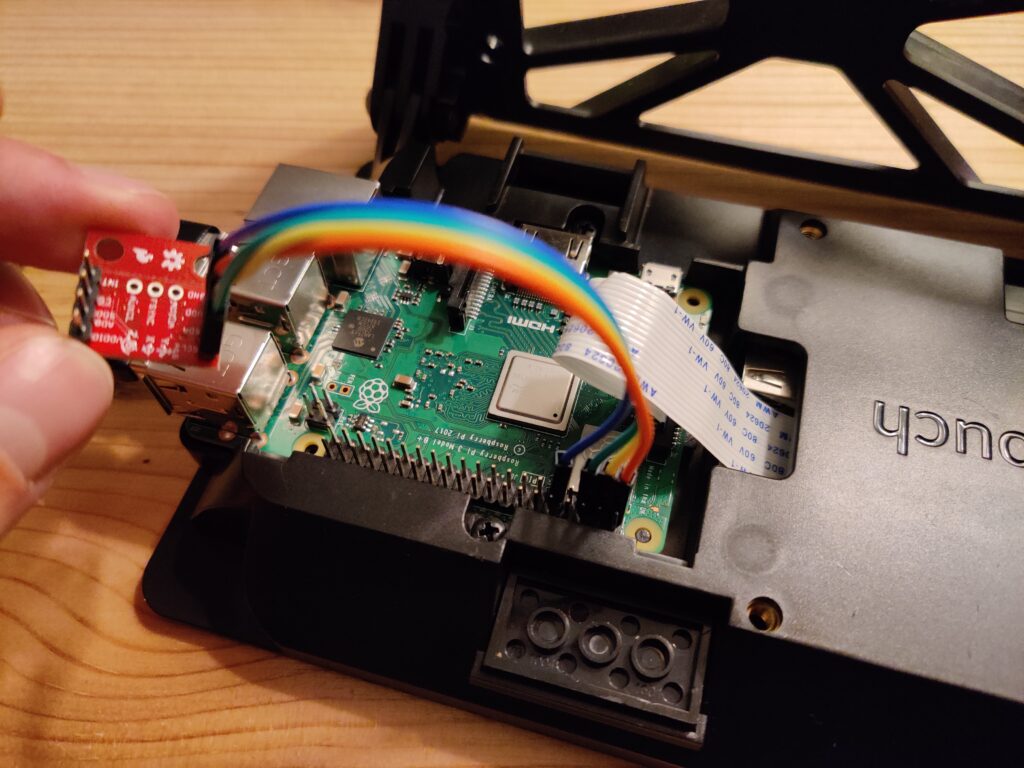
This week I’m trying out a different IMU, the MPU-9250. The Raspberry Pi communicates with this unit using the I2C protocol which is accessed through the GPIO pins on the Pi instead of USB. The purpose of the I2C protocol is to allow many peripheral devices to communicate with one or more controllers. On the Raspberry Pi, the two other options for protocols are UART and SPI. UART is intended for communication between only 2 devices and has no clock syncing. SPI can communicate from one controller to many peripherals, but uses many more wires that I2C.
I2C allows for communication between many peripherals and many controllers, has clock syncing, and does this all over two wires: SDA (serial data line) and SCL (serial clock line). So I2C is an ideal protocol for communicating with peripherals like the MPU-9250. The Raspberry Pi has GPIO pins for SDA and SCL lines, as well as power and ground.
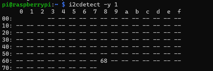
On the Pi, you can check what I2C devices are connected with the command i2cdetect -y 1. This shows the address of each device. Right now the MPU-9250 is at the address 0x68. This is the address to use for accessing the IMU in an application.
Up next I will be creating a simple program to read this data and sync it with the GPS!